| Title |
|
This section on earthquake resistant housing with reinforced concrete load-bearing systems consisting of RC frames
is currently being developed.
|
|
| To achieve improvement in planning of such houses three key
factors are discussed: |
|
|
| Building materials and construction process |
|
| Masonry Infilled RC Frames |
| To beginning of document |
| |
Where a frame of reinforced concrete or steel has masonry walls built right up to the
inside of beams and columns, a masonry infill panel is formed. Masonry infill walls can be constructed after completition
of the RC structure or simultaneously. In both cases the contribution of these walls to supporting gravity
loads is not taken into account in the design calculations. However in the context of earthquake resistance the construction
and detailing of the masonry wall and RC members is critical. The construction of masonry infills can have the following consequences
on the dynamic response of the structure
- increasing the lateral stiffness that may lead to increased seismic load
- in case of brittle failure of the infills induced extra dynamic load on the RC frame
- If not distributed symmetrically in plan shift greatly the centre of stiffness at each floor level resulting in torsional response
- cause weak storey if the number and layout of infills is not the same for every storey
- impede the displacements of the main RC members in cases where only partially built up and potentially causing short column failures
- cause unductile failure of the RC columns in cases where specific calculation for the most unfavourable masonry-RC frame interaction mechanism was not done
|
To achieve satisfactory performance of the structure there are basically two alternatives:
- Masonry infill is constructed as a partitioning non-structural wall. The panel is isolated from frame displacements by providing a flexible strip between the frame and the panel, filled with a highly deformable medium such as polystyrene. For this design a problem can be the face
strength of the wall as well as its out-of-plane stability.
- Masonry infill is constructed as a load-bearing element. In this case the contribution of the infills to the dynamic response and strength distribution needs to be calculated.
|
| A well conceived and designed RC infilled frame performs satisfactory. When the infills get damaged before
the development of high shear forces, closer to the shear resistance of the RC system alone, the infills damp the lateral motions and prevent large displacements of RC frames. |
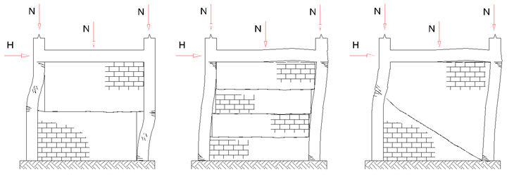
Observations of earthquake damage and experimental research indicate that the expected failures of low-rise RC infilled frames
is of shear type. The failure mechanism depends on the masonry infill to RC frame stiffness ratio, the strength of masonry units and mortar, the contact bond between infill and frame.
The following shear failure mechanism have been established:
- Shear of the infill in several horizontal layers allowing moreover unrestrained displacements of the columns. This mechanism allows plastic hinging of the columns at the beam-column joints.
- Shear of the infill along a single horizontal surface located in the middle of the infill. As a result approximately half of the height of each column remain restrained while the other half has to accomodate the lateral drift. As a result the free parts of columns may fail in shear in addition to the plastic hinging at the beam-column joints.
- Diagonal shear of the infill. This mechanism can occur when the strength of the masonry is high( comparing to that of the RC frame) and the interface masonry-concrete is well bonded. A windward column is partially supported from the infill and fails in shear. The leeward column is moreover unrestrained from the infill and fails by hinging at the beam-column joints.
|
| The last of the three discussed ultimate state faiure mechanisms will be used for the modelling of seismic behaviour of RC infilled frames in this section of the guide. |
| Seismic resistance verification |
| Seismic design loads |
| The dynamic response of the infilled RC frame can be determined in a number of ways.
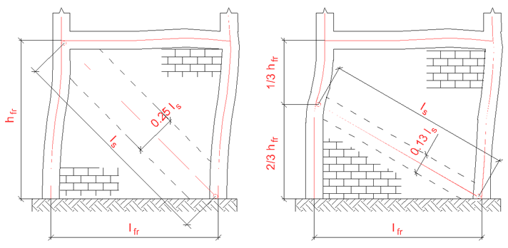
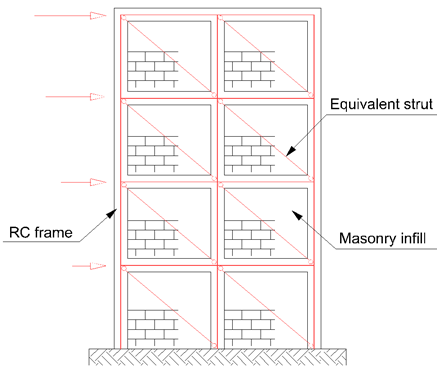
An ELF or modal analysis procedure may be followed modelling the infils as well as their interaction with the RC frame. Normally the structure is modelled at the stage when the bond between infills and frame has failed and the infills are represented by an equivalent compression member pinned to the frame. The location of the pin joints and dimensions of the equivalent compression diagonal are determined based on the expected failure mechanism, mechanical properties of infill and aspect ratio of the infill.
The correct stiffness of the equivalent diagonal strut should be input for the ELF or modal analysis of the model. The stiffness of the member depends on the type of diagonal shear of the infill. In case the strut connects the frame corners the dimension of the member in orthogonal direction can be taken as 1/4 of its length.
Alternatively the diagonal shear of infill can be modelled by a compression strut which supports the winward column at 2/3 of the infill height. In this case the equivalent compression member dimension in orthogonal direction is taken as 13% of the strut's length. After running the ELF or modal analysis procedure the main RC frame structure is designed( without account for strength contribution from the infills) for the determined seismic forces. |
| An alternative approach for determining the design seismic loads is outlined briefly.
The design seismic forces are obtained on the basis of a modified period of vibration of the fundamental mode of vibration of the RC frame.
The modified first period of vibration of the infilled frame is : |
| T1 = (T1b+T1i)/2 [s], |
| where the meaning of symbols is as follows: |
| T1 = the fundamental vibration mode period for determining the base shear from the design response spectrum, |
| T1i = the fundamental vibration mode period of the structure with masonry infill, |
| T1b = the fundamental vibration mode period of the RC structure, |
| According to EC 8 the fundamental period of vibration of a RC frame structure with masonry infills may be determined from the formulae: |
| T1i = T1b/SQRT((1+T1b2*Aw*G*g/16*HW)) [s], |
| where the meaning of symbols is as follows: |
| T1i = the fundamental vibration mode period of the structure with masonry infill, |
| T1b = the fundamental vibration mode period of the RC structure, |
| Aw = the average horizontal cross-sectional area of filler walls per storey in the examined direction, |
| G = the shear modulus of masonry infills, |
| g = 9.81 m/s2, |
| H = the height of the building |
| W = the weight of the building- self weight of the structure plus a portion of the variable load |
| After calculation of T1 and the determination of the ordinate Sd from the design respomse spectrum the base shear can be determined. The ELF procedure is followed to calculate the loads on the RC frame and design of its members.
No specific data regarding design of the masonry infills is specified in EC 8. |
|
| Planning and layout |
| To beginning of document |
 |
|
Figure 1- Determination of equivalent diagonal strut |
 |
|
Figure 2- Failure mechanisms for masonry infilled frames |
 |
|
Figure 3- Numerical model including the contribution of masonry infills |
 |
|
Figure 4- Vertical distribution of base shear |
|
| Details for seismic resistance |
| To beginning of document |
| To beginning of document |